68kMLA Classic Interface
This is a version of the 68kMLA forums for viewing on your favorite old mac. Visitors on modern platforms may prefer the main site.
| Click here to select a new forum. | |
| Reverse Engineering the Macintosh Plus PCB | |
Posted by: mg.man on 2021-07-23 01:19:28I've got this oddball Novy 020 early accelerator ... but will need a socketed 68000...Ooo... now you got me thinking... I have a Total Systems Mercury 030 that's in my SE atm, but is supposed to be configurable for a Plus. I believe you traditionally needed a Killy clip or "headers" soldered onto the Plus CPU. I'm sure you still need the 68000 to "kickstart" everything, but wonder if it might be possible to install headers on the Plus "board" and "mount" the 68000 on the Mercury 030 instead... Some serious soldering work, but might prove more reliable... interesting... Something else... I know 2Mb 30pin SIMMs exist - I have a couple in my LC II... I wonder how hard / complicated it would be to give the Plus one more address line?... I know... thinking out loud again... 😀 | |
Posted by: max1zzz on 2021-07-23 04:50:16I wonder how hard / complicated it would be to give the Plus one more address line?My understanding of this is that although the hardware modifications would be relativity simple it would require significant modification to the ROM as there isn't enough address space allocated to RAM by default. I'm no expert though so I might be wrong, this is something I half remember from threads I read years ago... | |
Posted by: mg.man on 2021-07-23 06:02:59it would require significant modification to the ROM as there isn't enough address space allocated to RAM by defaultYeah... I suppose if it was easily done, someone would have done it by now... Reading through some of the history around the original ROM-inator, it appears that up to 8Mb is allocated to ROM! Shame it wasn't the other way around. | |
| Posted by: bdurbrow on 2021-07-23 17:30:43 ROM, and probably the PALs also. | |
| Posted by: max1zzz on 2021-07-24 17:46:49 Hmm This board is being stubborn! I'm getting a checkerboard, No chime. I found I had a couple of address lines shorted together as well as a couple of missing traces for RAM data / address but fixing these hasn't resulted in a booting system I have spent some time comparing the layout to the scans of the board and haven't been able to find any more errors.... Is anyone aware of a decent scan of the plus schematics anywhere? The only copy I can find is such terrible quality I'm haveing a really hard time following it.... | |
| Posted by: mg.man on 2021-07-25 02:12:11 I believe the Bomarc ones are here... - https://www.macintoshrepository.org...i-iici-iicx-iifx-iisi-lc-ii-iii-quadra-840av- Is that what you're using? Also found this... - https://vintageapple.org/gamba2/images/plus_analog.PDF I'll see if I have any others... | |
Posted by: mg.man on 2021-07-25 02:13:24the Bomarc onesah... those might be the crappy "Apple" ones... lemme hunt some more... | |
| Posted by: mg.man on 2021-07-25 02:15:49 A thought... you do have the two resistors configured correctly for the amount of RAM you're using? I know it's a dumb question... but I've certainly torn plenty of hair out in the past thanks to my own "Homer" moments... 😉 | |
Posted by: max1zzz on 2021-07-25 04:44:25ah... those might be the crappy "Apple" ones... lemme hunt some more...Indeed they are A thought... you do have the two resistors configured correctly for the amount of RAM you're using? I know it's a dumb question... but I've certainly torn plenty of hair out in the past thanks to my own "Homer" moments... 😉I'm sure we have all been there 🙂 But in this case I have double checked it is correct, I have neither resistor installed and have 4MB installed on the board (And I took that 4MB out of annother mac that was working so i'm sure it works fine) | |
| Posted by: max1zzz on 2021-07-25 09:50:30 We have floppy! (And bong 🙂 )  I'm not quite out of the woods yet, as the floppy icon is not flashing and my FloppyEMU is not happy when I connect it (It shows a self test error "Check pin CLK0") so there must be some kind of issue in the IWM circuit that needs further investigation As for the issue stopping the board booting, I want to do some more testing before I commit to saying what the issue was, but the fix was this quick bodge:  It's a little hard to see as my camera would not focus on that tiny wire, but what that wire is doing is replacing the entire A3 trace. | |
| Posted by: mg.man on 2021-07-25 10:00:48 Well done!! Nearly there... 😎 | |
Posted by: Trash80toHP_Mini on 2021-07-25 11:18:29hmm..... now I'm trying to resist the urge to start modifying the board before I even know if the original design worksHEH! Figure out which parts can be switched to SMT (ROMs?) and you'll have real estate and enough clearance on the bottom of the board for low profile SCSI to somethingorother components with the SD card mounted in place of the programmer's switches. Feels to me like the card will align with the second cooling slot up and a WiFi antenna could stretch along within the next slot up, outside the RFI paint . . . . . . just saying. 🙃 | |
| Posted by: cheesestraws on 2021-07-25 11:36:04 Oh, very very impressive. Well done indeed. | |
Posted by: max1zzz on 2021-07-25 12:28:11Well done!! Nearly there... 😎 Oh, very very impressive. Well done indeed.Thanks 🙂 HEH! Figure out which parts can be switched to SMT (ROMs?) and you'll have real estate and enough clearance on the bottom of the board for low profile SCSI to somethingorother components with the SD card mounted in place of the programmer's switches. Feels to me like the card will align with the second cooling slot up and a WiFi antenna could stretch along within the next slot up, outside the RFI paint . . .Well a modified board with a built rom-inator is already on the cards, I guess I could look at adding something like a BlueSCSI on board as well 🙂 Annnnd: 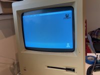 It boots from floppy! Turns out the filter network was damaged (Several elements where shorted and those shorted elements where then shorted to each other) I replaced it with 8 47ohm resistors and floppy now works fine 🙂 I'll order the correct filters for it at some point but this will do for now Now I need to go and find a keyboard and mouse (and fit all the connectors!) so I can test it fully 🙂 | |
| Posted by: mg.man on 2021-07-25 12:48:32 Super job, well done!! I guess I could look at adding something like a BlueSCSI on board as wellOr even just a 50 pin (internal) SCSI header would be useful. Something else to think about... the Plus can be a pain with SCSI devices, since it doesn't supply TERM POWER. I know @erichelgeson had to make some mods to his BlueSCSI to try and overcome that. Would be nice if that could be done to address that.. 🙂 | |
Posted by: cheesestraws on 2021-07-25 12:58:16the Plus can be a pain with SCSI devices, since it doesn't supply TERM POWER Well, there's even a footprint on the original board for a diode that will allow it to be provided, IIRC. So that at least shouldn't be a problem 😀 | |
| Posted by: mg.man on 2021-07-25 13:52:58 Well... I'm sure there was a discussion going on before the Great 68krash about an adapter that someone made up that could be used to provide a 50pin connector inside the Plus - for a BlueSCSI, SCSI2SD, etc... I'm also pretty sure the "board" was available somewhere (thingy verse?, etsy?, ??), but for the life of me I can't find it... I'll keep looking - but if someone knows what I'm on about, please put me out of my misery!... 🥺 | |
| Posted by: Trash80toHP_Mini on 2021-07-25 15:26:40 @360alaska developed an elegant adapter for that purpose as I recall. | |
Posted by: Scott Squires on 2021-07-26 14:33:25adapter that someone made up that could be used to provide a 50pin connector inside the Plus Are you thinking of Stephen"s CloneyClip? GitHub - Stephen-Arsenault/CloneyClip: CloneyClip is an open source replacement for Killy Clips.CloneyClip is an open source replacement for Killy Clips. - Stephen-Arsenault/CloneyClip
 github.com
| |
| Posted by: mg.man on 2021-07-26 14:36:08 No, IIRC, it was a small "board" that gave you a 50 pin header... Like I said, though... memory has faded so could be totally off! | |
| < 2 > |