68kMLA Classic Interface
This is a version of the 68kMLA forums for viewing on your favorite old mac. Visitors on modern platforms may prefer the main site.
| Click here to select a new forum. | |
| SE FDHD Restoration | |
| Posted by: LaPorta on 2019-07-07 15:12:42 Thank you AP, I cannot find any glass ones...perhaps not made anymore? I'll find the next best thing. What is your reference for what the lettering and numbering means? I'd like to see that. | |
| Posted by: Crutch on 2019-07-07 15:25:41 I stand entirely corrected, thank you AP. | |
| Posted by: AwkwardPotato on 2019-07-07 15:56:21 AFAIK the glass ones aren't made anymore, but luckily normal ceramics are still made with roughly the same dimensions. What is your reference for what the lettering and numbering means?I use a chart like this one: http://www.synthrotek.com/wp-content/uploads/2012/08/Capacitor-Codes.pdf | |
| Posted by: jimjimx on 2019-07-07 17:11:06 Wow. Great info. I tried to find this information years ago because one of them is missing from my SE SuperDrive.... I think it’s C10? Or maybe 15? Or 17? So long ago...... | |
Posted by: jimjimx on 2019-07-07 17:14:50Still looking for the speaker connector...I don’t have a SE around to measure right now, but, Is this your part? https://www.digikey.com/product-detail/en/te-connectivity-amp-connectors/640456-2/A1921-ND/109003 | |
| Posted by: LaPorta on 2019-07-07 17:28:18 I’ll measure, but that’s what it looks like! | |
Posted by: LaPorta on 2019-07-07 17:31:34I use a chart like this one: http://www.synthrotek.com/wp-content/uploads/2012/08/Capacitor-Codes.pdfThat’s great. It appears the code stands for first two digits, then 3rd digit is the number of trailing zeros in picofarads. | |
| Posted by: jimjimx on 2019-07-07 18:45:49 That one was 2.54mm This one is 3.96 mm https://www.digikey.com/product-detail/en/jst-sales-america-inc/B2P-VH-LF-SN/455-1639-ND/926547 | |
Posted by: LaPorta on 2019-07-08 19:25:26I don’t have a SE around to measure right now, but, Is this your part?These wound up being the right ones with tolerances of measurements of ~0.05 mm or so (I measured the one I have vs. the data sheet. I'll let you know how they work out when they arrive. | |
Posted by: jimjimx on 2019-07-09 00:54:40These wound up being the right ones with tolerances of measurements of ~0.05 mm or so (I measured the one I have vs. the data sheet. I'll let you know how they work out when they arrive.Well, let us ALL know how it works out.. Both here, and all over the internet, people talk about finding the right parts for old Macs and all kinds of other stuff, but never tell from who, where, how, and / or what is the modern replacement is. Like I said, I’ve got a SE SuperDrive with a missing glass cap as well, and nobody replied. That was 2 years ago. l think there was a server failure sins then, I can’t find the post. I have to dig it out and look at that board again.. So many things to do.... Right now I’m trying to figure out why my Tannoy i5 MP’s keep going into (what seems like) thermal shut down, and takes more than an hour to reset, even when cool... They did sound great. (I’m just frustrated, not really yelling...) | |
| Posted by: LaPorta on 2019-07-09 02:36:25 Well, to tell you the truth, I wind up trying to save as much of this information that I find out as part list files, or even writing them down in a notebook I have. No, I'm not "old" (I'm 35), I just have seen, like you, that information can disappear on the internet in the blink of an eye if one is not careful. I certainly will let you know what part and if it works out. | |
| Posted by: LaPorta on 2019-07-14 19:14:28 Small Update: Awaiting my new speaker connector and capacitors from Mouser, they should be here tomorrow. In the meantime, I took to removing the rust from the rear screw-in bar at the back of the logic board. If you look at some of the first pictures from my original conquest post (first photo here), you can see that the bar was literally coated with rust and corrosion. As I have attested to before, the product EvapoRust is incredible. I immersed the bar (after removal) in it for 12 hours, and literally all rust dissolves as can be seen in the first photo. This saves you from doing any manual labor removing the rust. In something this heavily rusted, it also leaves pits in the metal where rust literally ate into the bar, but that is unavoidable. The next step is gently scrubbing the surface with 0000 steel wool (second picture), and then buffing with Black coarse compound with a buffing wheel on a Dremel tool (subsequent pictures). I'm not making it a mirror finish (that's not how it was made), so doing this without sanding works fine. You can see that it looks far better than the originals. View attachment 28532 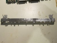  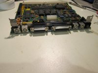 | |
| Posted by: LaPorta on 2019-07-20 10:04:55 Ok, much larger update now. I have made many repairs to the logic board. I repaired all the rotten traces that I could find, either jumping them or soldering across from a terminal to a now exposed area of the trace. I then checked those for continuity. I replaced C4, C5, C10, R1, and R6 because they were either open or out of spec. I also replaced the speaker terminal (thanks to those who helped find that). Lastly, I soldered in a new 1/2AA battery holder. After all of that work, regrettably, I am no closer to the machine working. Upon power-up, the fan spins, disk drive motor runs for a second like any compact, HD spins up, and CRT comes up. I then get the vertical line pattern seen in the final picture. There is no startup sound. I will continue to check traces and verify continuity, but are there any suggestions as to what may cause something like this? 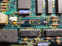  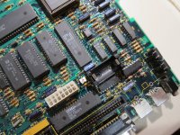 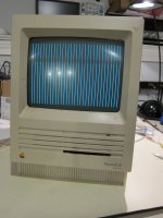 | |
| Posted by: LaPorta on 2019-07-20 19:13:35 Well, I resoldered a few points, replaced R9 which appeared to be faulty, cleaned and reseated all of the ROMS...and now I get no video at all. Sigh...not sure how I made it worse. | |
Posted by: dcr on 2019-07-20 19:19:54Well, I resoldered a few points, replaced R9 which appeared to be faulty, cleaned and reseated all of the ROMS...and now I get no video at all. Sigh...not sure how I made it worse.That's what happened to me when I resoldered the analog board on my Mac Plus. I went from getting video when I tapped on the side to no video at all. I went back and resoldered all the spots I had resoldered before plus any spots that looked in any way imperfect. It's worked since then. | |
| Posted by: AwkwardPotato on 2019-07-20 19:30:29 Weird... just guessing, maybe the battery leak damaged the ROM sockets and reseating the chips broke another one of the connections? | |
| Posted by: LaPorta on 2019-07-20 20:09:58 I re-verified each and every pin on each socket for continuity...all are good. The next thing on my radar is this "8530 SCC" IC....basically, I don't know what the heck it does, but it is the last thing that I can see that may play a vital role that was near the battery that might not work. I have verified all the traces I repaired vs. the companion logic board I have and they check out. The only thing that I could figure otherwise is maybe an IC itself is shot, and that I don't know how to prove or disprove. | |
| Posted by: oldappleguy on 2019-07-20 20:29:13 I have a se fdhd mother board I can send you. Just pay the postage. It's a new old stock in a sealed static bag. 661-0536 part number. | |
| Posted by: LaPorta on 2019-07-21 03:33:56 oldappleguy, your offer is most gracious. I do have a donor board if I need it, I was just hoping to have this one work out. I'll try a bit more...if not, it may just become one of my scrap practice boards! I wish I had TechEdison and thoise guys here with suggestions! | |
| Posted by: BadGoldEagle on 2019-07-21 04:55:44 What kind of voltages are you getting around the floppy port? Did you patch the big trace and its via (shown in red in the picture below)? I can't see it on this side of the board, perhaps you patched it from the solder side? 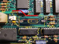 If it was, then I would check the voltages on each chip (not the filters of course, they aren't needed for now). If all checks out fine, then I'd take the oscilloscope to the CPU to check if the reset line is not stuck or something... The ROM and/or its socket could also be bad. | |
| < 2 > |