68kMLA Classic Interface
This is a version of the 68kMLA forums for viewing on your favorite old mac. Visitors on modern platforms may prefer the main site.
| Click here to select a new forum. | |
| Macintosh Plus Internal Hard Drive *Mod* | |
| Posted by: tt on 2012-10-11 12:25:02 Nice blog post on adding internal SCSI to a Plus: http://www.artmix.com/wordpress/?p=185 :b&w: Interesting to see he is using a SCSI / IDE adapter that looks like it's not his own design. 😀 | |
| Posted by: Trash80toHP_Mini on 2012-10-11 12:32:42 IIRC, there was a picture of a baffle for the chassis of the Plus posted here. It came with the Radius 16 and re-directed airflow over the A/B as the MIA Twiggy Drive Cover Box was apparently meant to do in the original design. re-creating the baffle effect and using a fan to air u[p that slot and across the A/B there would be the ultimate cooling hack . . . . . . IIRC. :?: | |
| Posted by: uniserver on 2012-10-11 12:44:55 I would like to get ahold of that document he has there… (English Readable) http://translate.google.com/translate?hl=en&ie=UTF8&prev=_m&sl=auto&tl=en&twu=1&u=http://www.artmix.com/wordpress/%3Fp%3D185 incase the blog goes down. 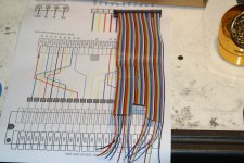 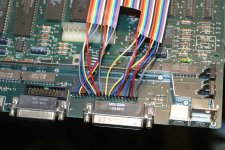 | |
| Posted by: tt on 2012-10-11 12:59:45 Maybe post a comment or send him an email, and he might be willing to post it. Most of the info is there in the two photos (the one with the tool over the page also), but having a printout while doing the work would be helpful. The rainbow ribbon cable really helps with this kind of job. 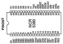 | |
| Posted by: uniserver on 2012-10-11 13:31:46 ok thanks TT does anyone else want to do this mod as well ? i am going to start soldering tonight. i don't have a multicolored scsi cable… but i think i can visually figure this out. | |
| Posted by: Trash80toHP_Mini on 2012-10-11 15:44:52 I'll add my two bits in on the ways to go about this hack. Stop by a CrapShack on the way home and buy a header strip to solder to the chips legs, it's not only more elegant to hack the cable at the IDC connector instead of the way it's done in the picture, it's a far more robust connection besides the reasons delineated above. free advice: ALWAYS take tomlee59's advice . . . . . . take trag just as seriously . . . . . . it's pretty well known around here that I have no aversion whatsoever to nasty, ugly, ill-advised hackery. Buy the header strip. [}🙂] ]'> | |
| Posted by: techknight on 2012-10-11 16:53:44 Yes, i agree with everyone else. You need to buy a row of male header pins and solder them streight to the chip. I posted the picture of the headers just in case your not sure what headers we are all talking about. Solder that strip right to the chips legs. Then you can fabricate your cable and solder to the female header. I also posted that picture too. This way, the thing can be unplugged. If you want to put the female headers on the chip and male on the SCSI cable, thats fine too and i actually recommend that over the other method, so if the mod is reversed, your connector wont short to the chassis. 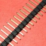 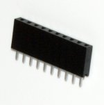 | |
| Posted by: tt on 2012-10-11 17:37:45 If a soldered header on top of the chip clears the chassis when sliding out the logic board, it sounds like a good idea. Is there clearance? Either way soldering directly to the chip is pretty hack-ish, but hard to get around. | |
| Posted by: uniserver on 2012-10-11 18:45:26 i can solder the header tips then bend it over (facing the front of the computer) then it should be aiming in the right direction where it will not get hung up on anything. literally the female part will be laying on the top of the scsi chip. | |
| Posted by: techknight on 2012-10-11 19:53:38 They sell 90-deg headers so you dont have to do that. | |
| Posted by: uniserver on 2012-10-11 20:08:54 and again i can get this stuff at radioshack? | |
| Posted by: tt on 2012-10-11 20:18:47 The metal bar on the logic board behind the chip might get in the way. | |
| Posted by: uniserver on 2012-10-11 20:32:10 Ok, I just looked and yes there is going to be some clearance issues. 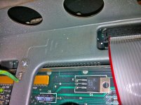 so 2 things, 1) - maybe no bend, or if so just slightly and not an angle 2) - i will have to slice the scsi cable into strips somewhat, to make it more flexible | |
| Posted by: uniserver on 2012-10-11 21:23:14 wish me luck i'm doing some good old fashion counting/snipping wires. Stole this cable from my 8600/200 parts machine. 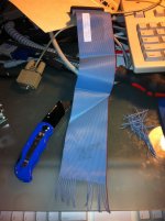 | |
| Posted by: uniserver on 2012-10-12 00:44:45 ok i triple checked all my solder joints/wire positions., tried changing the SCSI ID, Tried it with and with out termination... tried it with external hooked up and terminated, cant get it to work, even tried 2 different hard drives... if i disconnect everything and plug in just my scsi zip external it still boots so i know the scsi chip is working . i'm stumped. in his picture it looks like a different scsi chip then mine. 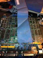 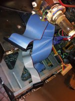 | |
| Posted by: tt on 2012-10-12 00:52:59 Did you check your power cable and verify voltages? | |
| Posted by: uniserver on 2012-10-12 00:56:07 yeah the hard drive spins up just fine, psu is good hooked it up to a 80gig sata drive and it spun up and detected fine through usb, g4mdd and i even put electrical tape around the cable to make sure none of the cut wires were shorting on anything. | |
| Posted by: tt on 2012-10-12 01:06:14 I haven't looked at the routing, but assuming it's correct, maybe check continuity from end to end? I'm thinking cold solder joint or something odd with the cable. | |
| Posted by: uniserver on 2012-10-12 08:43:57 right, i mean it should work, fairly straight forward. well i am purely copying what he already did, and everything i did is solely based on his cable in the pictures. i thinking thinking maybe, i need to get the document and try to figure out what goes were my self instead of copying. | |
| Posted by: trag on 2012-10-12 09:28:19 I'm not sure you've got the clearance for it, but here's an older posting about putting the same kind of header arrangement on the 68000. The 53C80 would be just the same but with a smaller socket. http://68kmla.org/forums/viewtopic.php?p=160782#p160782 Also, keep in mind that you can change from sliding the logic board in and out to inserting it more directly. Put one edge (left of right) of the logic board in the Macintosh frame rails. Then use a flat head screw driver to gently pry the other side of the frame out just enough to let the other edge of the logic board slip into its rails. This is how the logic boards are installed and removed when they have a big honking upgrade sticking out on top. | |
| < 2 > |