68kMLA Classic Interface
This is a version of the 68kMLA forums for viewing on your favorite old mac. Visitors on modern platforms may prefer the main site.
| Click here to select a new forum. | |
| Reverse Engineering the Macintosh SE PCB & Custom Chips for 1:1 reproduction | |
| Posted by: Kai Robinson on 2020-08-19 23:56:43 Also - I'd like to say thanks to @rplacd for the kind donation to the cause - YOU RULE. | |
| Posted by: quorten on 2020-08-20 02:37:40 You could tentatively count me if you're taking tentative counts. I'm still working through a different soldering project to prove to myself I'm not too much of a soldering newbie when it comes to soldering complex "computer-grade" electronics with lots of through-hole connections. Yeah, still something I need to think about overall. Something along the lines, I would be interested if I could. | |
| Posted by: techknight on 2020-08-20 05:11:34 Im in for an SE/30 board. When you get to that project, I have 3 or 4 dead ones of those. | |
| Posted by: Busterswt on 2020-08-20 14:06:26 @Kai Robinson I’ll be your huckleberry. I have a donor board (albeit, with no known battery damage) and an underutilized Hakko FR-300. If you’re still looking for paying volunteers, lemme know. | |
| Posted by: Kai Robinson on 2020-08-20 18:26:23 @Busterswt Well, PM if you wanna make a donation - and if you want a board for the SE, let me know there, too. | |
| Posted by: Bolle on 2020-08-26 02:08:18 Had some time to grind away at one of my spare boards:  Going all the way down to the inner layers is going to be an absolute pain in the back. I'll need to stock up on wheels for my grinder first. Also it looks like the additional signaling two layers are right in the middle of the boards hidden under yet another set of VCC/GND plane layers. | |
| Posted by: LaPorta on 2020-08-26 02:32:24 Bolle, seeing your photos truly makes one see just how much damage battery acid causes, and just how damn near impossible it would be to repair such damage externally. Alternatively, however, if you guys scan this stuff in at each layer and make a diagram of what goes where, then the poor soul looking for the other end of a rotted trace actually will have a shot of bypassing it if he knows where the heck the other end is. | |
| Posted by: quorten on 2020-08-26 05:41:55 Looking pretty good, with a few more photos someone would be able to run and do another PCB layout for the Macintosh SE/30 main logic board! No need to wait around for the Macintosh SE boards to be finished. Mentioning that, it would also be really helpful for making improvements to the redrawn Macintosh SE/30 schematics. I noted elsewhere in this forum I started making improvements to fix some of the errors pointed out in the previous versions. | |
| Posted by: ajacocks on 2020-08-26 11:12:55 Wow, this is so amazing! I’d also like to build one of these prototype SE boards. - Alex | |
Posted by: techknight on 2020-08-27 04:13:55Had some time to grind away at one of my spare boards:Yea, I know. You almost need a milling machine. Like what they use for doing engine heads. If you know the layer depths, you could program the machine and setup a routing bit and vacuum nozzle head and let it rip. | |
| Posted by: Bolle on 2020-08-27 04:42:36 Getting the board stuck down evenly would be a challenge though. I do have a DIY-hack CNC mill and in theory the step size should be accurate enough to take off a layer. I guess it’s worth a try. I have enough dead boards here to play around. In the end careful grinding might be the best option though I think. | |
| Posted by: wanderingjew on 2020-08-27 10:23:37 If you want to get a look at the inside layers of a PCB, you *can* use a small CNC mill with a small step size. This is probably the best example of that: https://www.youtube.com/watch?v=iV4LJX1HdPk However, there's a significant drawback going the CNC route if you don't have it perfectly flat. Half of the board will have the traces you're interested in, while the other half will cut too deep or too shallow. There's a lot of fixturing needed for this project. I have heard of people going to a machine shop and using a surface grinder which would be a very good option if you could bond the PCB to a flat piece of steel (for the magnetic clamping). Alternatively, you could also find a machine shop with a _huge_ lapping machine. That would give you the ability to cut perfectly perpendicular through the plane of the PCB. | |
| Posted by: Kai Robinson on 2020-08-27 17:06:50 SE/30 stuff, i'll break out into a separate thread, so we can concentrate on the SE/00 board here - sorry if i've been quiet, been enjoying a few days 'staycation', visiting friends etc. I'm back home tomorrow - so will get PCB's shipped out on Monday. | |
| Posted by: Bolle on 2020-08-28 00:04:30 I guess this is as good as it gets... oh boy what a mess. At least you can see both signal layers so I don't have to bother and get to the other side as well. 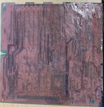 Damaged some traces but together with the schematics it should be easy to reconstruct those. | |
| Posted by: Kai Robinson on 2020-08-30 04:27:56 I am back from a week long staycation, and I have to say the new boards look even more amazing than the first batch did! So far the rear i/o power seems good and the GND and +5v for the 68000 and 74ACT257's is now there, along with the correct GND and +5v for the floppy and scsi, now... Just need to build one this week - they look amazing with new SIMM sockets, too! 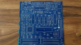 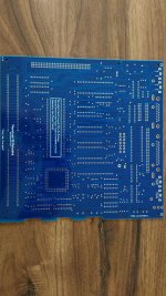 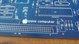 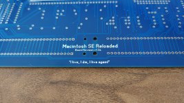 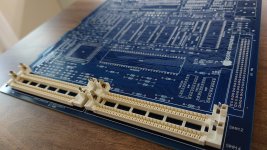 | |
| Posted by: pax on 2020-08-30 05:46:29 Spectacular! | |
| Posted by: ravuya on 2020-08-30 07:23:20 That looks incredible. | |
| Posted by: rplacd on 2020-08-30 07:29:38 Gorgeous. You have no idea how relieved I am to see the metal clips on the RAM sockets! | |
Posted by: techknight on 2020-08-31 03:19:08Gorgeous. You have no idea how relieved I am to see the metal clips on the RAM sockets!Yea, I know, right? | |
| Posted by: Kai Robinson on 2020-08-31 07:15:32 Okay, been at it for 14 hours and this is as far as I've got... Need a few more parts to finish it off! My eyes have gone funny...! 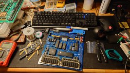 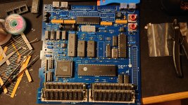 | |
| < 12 > |
