68kMLA Classic Interface
This is a version of the 68kMLA forums for viewing on your favorite old mac. Visitors on modern platforms may prefer the main site.
| Click here to select a new forum. | |
| Radius Pivot IIsi adapter for SE/30 PDS | |
| Posted by: BadGoldEagle on 2017-06-20 06:10:13 Hey Been working on an adapter for the IIsi Pivot. The Pivot itself works like a charm but unfortunately as you may or may not know, it does not fit inside the SE/30 case... 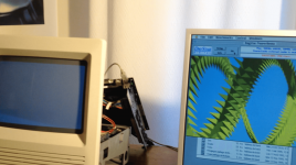 The adapter consists of two 120 pin EURO DIN adapters and 120 traces on a single layer board. Should be pretty easy. I have all the dimensions and I have a pretty good idea on how to arrange the traces. So yesterday I started work on a PCB using KiCad (since Eagle went bust, I thought I might be better off with something that will continue to exist for quite some time). First I had to create the 120 pin EURO DIN connector layout and footprint since KiCad's standard library doesn't have them. It took me quite some time to get there (I am a COMPLETE NOVICE when it comes to designing PCBs). It's done but I think something is wrong with them... When I launch the PCB design tool, I import the NETlist and the two connectors appear on top of each other. I can move them all right. I can also start a trace on any connector but I can't end the track anywhere!!! Not even on the same connector! I added some wires to the schematic file (which looks awful BTW because I don't know how to arrange the inputs correctly since this connector has 3 rows of 40 pins) and re-annotated the file, created a new netlist, and re-imported the netlist but I still get the same error: Trace near pad! Of course it should be near a pad, in fact it should be on it!! So I'm stuck. Any idea on what's wrong? Here are my files: KiCad.zip Once that has been taken care of, the rest is pretty easy. Draw a couple of lines, add dimensions and that's it. This adapter would be pretty useful since these IIsi cards only cost 4 bucks! And Macmetex stocks hundreds of these! Having a single layer PCB made isn't that expensive either... So this would allow people on a really tight budget to add color to their SE/30! That'd be awesome, right!! Plus that IIsi Pivot card is compatible with a lot of displays including LCDs! Any help appreciated! | |
Posted by: Themk on 2017-06-20 06:54:09First I had to create the 120 pin EURO DIN connector layout and footprint since KiCad's standard library doesn't have them.You could have asked me for my KiCad footprint files that I have been using over in ProtoCachex. [😛] ]'> Also, you mentioned you were a novice, so let me give you a few tips: * Single layer PCBs are NOT your friend. I know they are slightly cheaper, but not enough to justify their limited usefulness. If you are doing this, do it right. While you may route all the signals on one side (layer), you want to give yourself plenty of space for big power and ground traces. * I haven't taken a look at your KiCad files yet (I'm on vacation), but don't worry, I will today. I'll try to go snag my JunkTop laptop later and see what's going on Until then, here's some stuff for you to mull over. | |
| Posted by: Trash80toHP_Mini on 2017-06-20 08:30:23 Very cool! How about a screen shot of the layout to see for those of us who aren't even up to the novice level yet. edit: If you can route the traces on two layers for testing purposes that's great. The passive SuperMac RA adapter for using their SE/30 form factor card is a four layer board. That's the only way to go for production boards. What's the size of your board? | |
Posted by: BadGoldEagle on 2017-06-20 09:14:46You could have asked me for my KiCad footprint files that I have been using over in ProtoCachex. [ 😛 ]I definitely should have. I've just had a look at the thread and these connectors look great! Well, better late than ever, right... While you may route all the signals on one side (layer), you want to give yourself plenty of space for big power and ground traces.Pardon my ignorance but which ones are which? I can't seem to find the 030 PDS pinouts. The ProtoCache project looks so professional, so you must have them, right? I was planning on making all traces equal (so I wouldn't have to worry about those power and ground traces)... But that was probably a mistake. I don't have my card with me ATM, I should be able to tell which ones are which just by looking at them... But pinouts would definitely help. * I haven't taken a look at your KiCad files yet (I'm on vacation), but don't worry, I will today. I'll try to go snag my JunkTop laptop later and see what's going onWell, prepare yourself to being blown away by the shear ugliness of the thing. It looks everything but professional. Basically this is a big right angle adapter. Here's a picture of what it would look like. Again, it looks like something a first grader would do but I've tested it and the Pivot will fit perfectly that way with ample room for the DB-15 cable 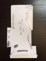 | |
| Posted by: BadGoldEagle on 2017-06-20 09:22:41 Trash, you asked for it, and here it is. 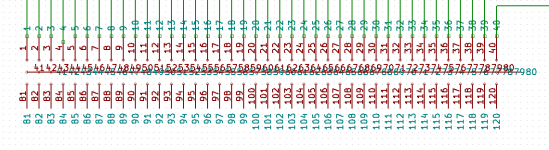 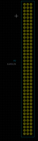 That middle row is the thing I was referring to as awful. And since I don't have any pinouts to work with I named each pin individually 1 through 120... The footprint file doesn't look that bad, and the dimensions are correct at least... But it doesn't work, so it's useless for now. I am now on the PCB Designer Hall of Shame (right on top I should add) and on that note I'm going to sign out and delete my profile. jk :lol: | |
| Posted by: Trash80toHP_Mini on 2017-06-20 09:34:33 😉 Snag the pinouts for the PDS connector from my most recent ProtoCache .PDF file attachment. If you're working from the component side, everything will be mirror imaged, but it's way better than nothing. I'm pretty sure everything its right, but proofreading by someone else would be greatly appreciated | |
Posted by: bigmessowires on 2017-06-20 13:06:54When I launch the PCB design tool, I import the NETlist and the two connectors appear on top of each other. I can move them all right. I can also start a trace on any connector but I can't end the track anywhere!!! Not even on the same connector!I don't have KiCad so I haven't looked at your file, but you need to have the desired pin-to-pin connections already made in the schematic file. Then you can use the PCB tool to route each connection, defining the exact path it takes on the board and its trace thickness. You can't just connect arbitrary pins from within the PCB tool if they aren't already connected in the netlist that was imported from the schematic. I'm not sure if that's what's happening, but from your description of the problem it sounds like it. | |
| Posted by: BadGoldEagle on 2017-06-20 14:31:39 Hi BMOW. I forgot to say in my previous post that I did do that (at least on one row: that's the green lines you can see on the first picture), but that didn't work either. But thanks for the tip! I think the footprint file is bad. | |
| Posted by: Themk on 2017-06-20 17:14:37 Well for some bad news that I also relayed in the ProtoCache1 thread, I left my project files at home by accident. So, BGE, that means that I you will have to wait a little while longer in order to get my layout files. I don't have access to them until the end of my trip, when I return home. The good news is that I am looking at your KiCad files right now! | |
| Posted by: Themk on 2017-06-20 17:38:35 Oh and BadGoldEagle, The pinouts for the 030 PDS are in both the BOMARC schematics, and also somewhere in DCaDftMF(3e). | |
| Posted by: bigmessowires on 2017-06-20 20:19:29 I took some photos for you - hope this helps. 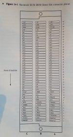 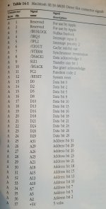 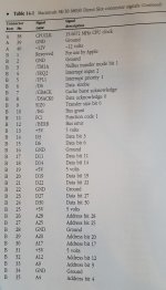 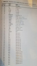 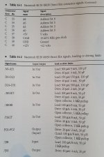 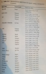 | |
| Posted by: Trash80toHP_Mini on 2017-06-20 20:44:44 Ya beat me to it! [😉] ]'> You may have seen this, if you've not taken a good look at existing passthru cards, the rows are mirrored (A flipped with C) on the passthru as compared to the PDS pinout, so just in case: /monthly_01_2017/post-902-0-53097100-1485883247.jpg">View attachment 11533 Looks like your board heads completely around so it's perpendicular to the MoBo connector, while the DiiMO card just starts out angling that way. Your connector/pinouts will match. It'd be a good idea to throw a second slot on there at approximately the position of the IIci Slot on the DiiMO while you're at it. Pretty sure it's located there to clear the HDD bracket, but I've never actually seen one IRL. [🙂] ]'> | |
| Posted by: BadGoldEagle on 2017-06-22 08:59:07 Thanks for the pics BMOW! The first one is super useful! Now I know what side of the male connector row A is. Great. Looks like your board heads completely around so it's perpendicular to the MoBo connector, while the DiiMO card just starts out angling that way.Yep, otherwise the IIsi Pivot won't fit properly... It'll fit if it's slightly crooked but then there would be no way to connect the DB-15 cable... I don't know how tall the IIci PDS cards are but the way I designed this adapter, there would be plenty of space left to accommodate some other cards (there's about 5cm left once the IIsi card is installed. I can't really make that gap any bigger because, again, I wouldn't be able to plug that DB-15 cable into the card... BTW, once this is finished I'll make a pinout of that cable since it is pretty rare and I happen to have one). So I think we don't need a second port. And I don't even know if it'd be possible to plug two cards into the same SE/30 slot without making some sort of hack. (There's no way it'll work without some proper engineering work IMO, but I think if someone wants to plug in more than one card, they'll get a Protocache 😉 ) I should have taken a pic of the "test card" installed. And unfortunately, I don't have the SE/30 with me ATM, but let me tell you it looks great. Themk, take your time, there's no hurry. Don't bother checking my files, yours are 100000% better I'm sure. BTW, enjoy your stay in Blighty 😛 Next time you (or any one of you guys) stay in France, beer's on me. | |
| Posted by: joethezombie on 2017-06-22 10:29:02 I don't have anything to add, but i am watching this thread closely, because it's all kinds of awesome! BTW, is French beer any good? | |
| Posted by: Trash80toHP_Mini on 2017-06-22 11:46:52 IIsiColorPivotII_PDS_Card_HackProject™ Header Chopping | |
| Posted by: Trash80toHP_Mini on 2017-06-22 16:21:16 I've been looking for an excuse to doink the front bezel into Illustrator, forgot to add the Slot Bracket though. :-/ 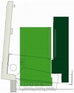 Is this how you're going about fitting it? | |
| Posted by: Trash80toHP_Mini on 2017-06-22 19:28:53 Couldn't resist finishing up the chassis. There wasn't really room for a second PDS on the card in the pic above. For ProtoCacheX, I was trying to stick the ass end of the RCPII/IIsi out the slot with no luck. Desoldering the connector isn't the problem to fit it out the hole in the case. I just couldn't get the height right. Playing around with the chassis/bezel/dead board to get the bracket graphic done I noticed something peculiar, the tail end of the card fits down into the extra slot in the chassis at right angles to the PDS with plenty of clearance for the CRT Neck/Board/Yoke. This is what happens when you head insists on flipping everything about every which way: 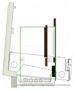 SideCards™ I haven't got scans of the RCPII/IIsi or the Asante NIC for a proper representation, I'll do that tomorrow at work. So I just roughed in the cards from a tickmarked .100 ruler I made on a post it note and scaled them into the graphic. The actual NIC nestles between the pointy part rows of the Yoke, but it'll have to be raised a bit so that the FPU socket clears the top of the FDD cage. But everything fits well enough. Does anybody actually use that horrid stock HDD bracket/sled? Didn't think so. 😛 The Asante Mac Con 30 with the removable passthru card for ThickNet is killer in combination with the Pivot Card. DA-15 or HD-15 (with a bit of sheet metal magic) bolt right up in place of the lockdown DA-15 for ThickNet for the neatest, cleanest of installations. | |
| Posted by: Trash80toHP_Mini on 2017-06-22 20:22:26 Red line in the PDF's the wire wrap prototyping blank in the ProtoCache1 pics. It's juuuust big enough for me to throw together a SideCards™ mockup. Chassis-Bezel-002.PDF I hope you don't mind me making crazy suggestions for your project, I can't help myself, if any of this works, it's all yours. 😉 | |
Posted by: Trash80toHP_Mini on 2017-06-24 10:16:21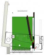 Well it's insane, but what else is new? I got SideCards™ to fit even when using that horrid stock HDD sled. Clearances will be something less than 1mm to barely touching, hence the traditional SE/30 expedient of electrical taping the chassis at the points indicated by the arrows.Angling the Pivot Card a smidg toward the rear would provide a bit of clearance, but where's the challenge in that? The cable connector is a perfect fit between the chassis and HDD sled, sweet coincidink! The Asante Mac Con ie fits when angled as well! [😀] ]'> | |
| 1 > |